Coplanar Waveguide Transmission Line

As a result of the large amount of RF work I was doing over the summer, as well as the VSWR theory I have been exploring in my own time, I felt the need to design a small coplanar waveguide transmission line so these concepts could be tested practically.

Coplanar Waveguide of Impedance: 50Ω

The idea is to probe along the length of the exposed trace in order for the standing wave (present at a given load mismatch), and therefore the power transmission, to be visualized via a scope, hence the peeling back of the mask along the trace and the coplanar ground.

As better lab equipment makes itself available to me I’ll be returning to this PCB and taking more detailed measurements but until then, and in the near future, I’ll need to find a variable load solution to take initial measurements with.

VoltOk MINI (Linear-to-Exponential Signal Converter)

This board was a long time in the making, starting off as part of a larger synthesiser project that had to be dialed further and further back with respect to available time over the summer it was going to be built. The original board had more than a few stages: the converter, two VCO’s that would be fed by it, a wave shaper for each VCO output and a mixer to combine these before output. While the mixer was successfully prototyped, as well as the VCO’s (as standalone breadboard circuits), the wave shaping circuitry proved more difficult and was left for a later iteration of the entire design.

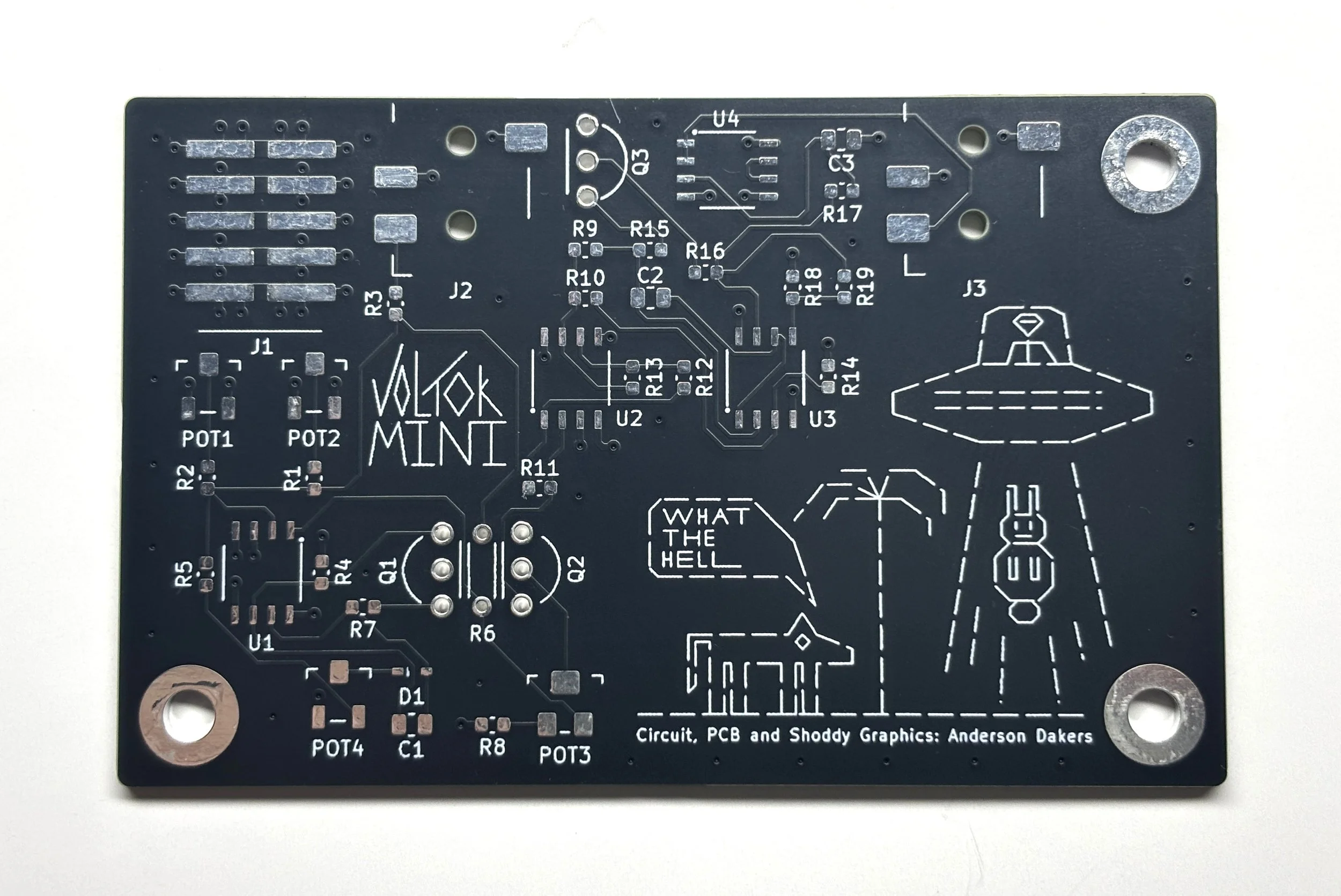
In the end the converter and VCO made up the entirety of the PCB, this being the first iteration of the board, seen below, unpopulated.

VoltOk MINI Mark I

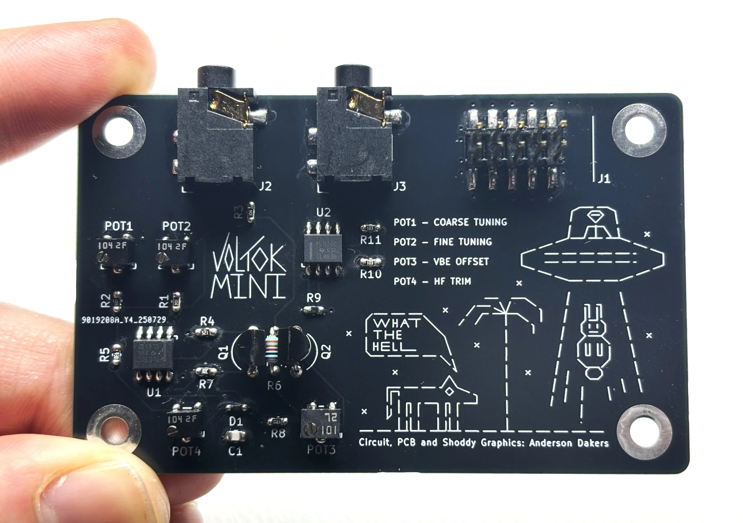
While the routing is somewhat messy I was very pleased with the layout, after going through about ten unofficial iterations in KiCAD. This was however irrelevant in the end, as pleased as I was with the layout (as it was) and graphic design, the thing did not work. Or at least it half worked, the converter behaving as expected but the VCO not at all, despite a working breadboard and SPICE simulation of the exact circuit laid out on the breadboard. It was suggested that stray capacitance in the board itself was perhaps throwing off the analogue feedback loop that made up part of the VCO however, I was also advised not to waste countless hours trying to trouble shoot this particular problem and at this stage, was happy to follow that advice.

In light of this, but still determined to have a working PCB by the end of the summer, I stripped back the schematic to just the converter and remade the board with only this circuitry in place.

VoltOk MINI Mark II

To no shock at all, this board worked, despite the routing making less sense now that a lot of the additional circuitry had been removed. Also, despite the focus of another project being power distribution (even more specifically bypass capacitors), not a SINGLE bypass capacitor made its way onto this board, something I realised after the population of the Mark II. This infuriates me but gives me something else to add to the full synth project when I get to it.

808 Kick Drum Generator

The first PCB I made from scratch, from schematic to finished product, it worked to varying degrees throughout the development process but never very well. It was based off the original Roland TR808 drum machine circuitry, using a Bridged T-Network to create a transient oscillation. A short, low frequency pulse that sounds like a kick drum.

This board taught me a lot of valuable lessons, all of which stem from its non-function.

  1. Always prototype the circuit first, no matter the confidence you have in your simulations and/or established circuit designs.

  2. Build up a library of specific parts rather than using the generic footprints and symbols provided with the chosen CAD software.

  3. Don’t trust found-online library parts. My IDC header had to be flipped so the shroud lined up correctly as the file I found was designed for a bottom mounted header, not top.

  4. Through-hole components are more painful to solder than surface-mount, contrary to what I originally thought.

  5. Reworking boards is quite the annoyance and the more steps taken to minimize this the better. In other words, further emphasis on my first point.